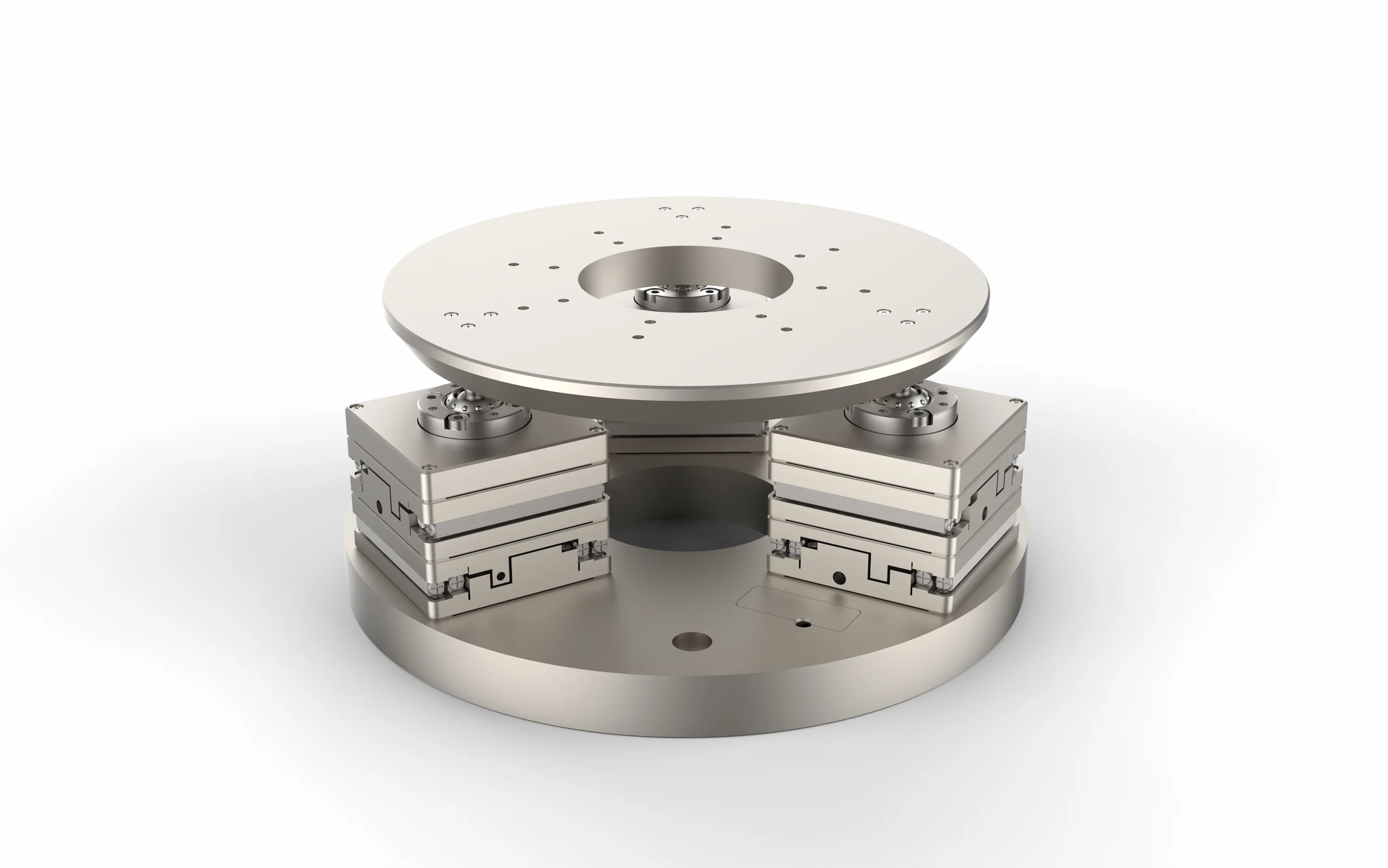
X, Y and rotation around Z
GO XYR
Center and rotate a component in a plane
- Travel
- X/Y ±10 mm · R ±10°
- Load
- 10 kg centered top load
PRECIBEO GO 3-axis stages
Precision alignment in three degrees of freedom
Center, rotate and level your components with PRECIBEO GO three-axis nanopositioning stages. Piezo walking drives combine high force with 2 nm linear minimum incremental motion, smooth continuous movement and self-locking at rest.
2 nm
Linear minimum incremental motion
±10 mm
Linear travel
±10°
GO XYR angular travel
2.5 kg
Maximum GO TipTilt lift
10⁻⁴ Pa
High-vacuum versions
Choose the right motion
A three-axis positioning stage controls three independent movements. Choose GO XYR for planar alignment, GO TipTilt for vertical positioning and leveling, or a GO XYZ assembly for three-axis translation.
X, Y and rotation around Z
Center and rotate a component in a plane
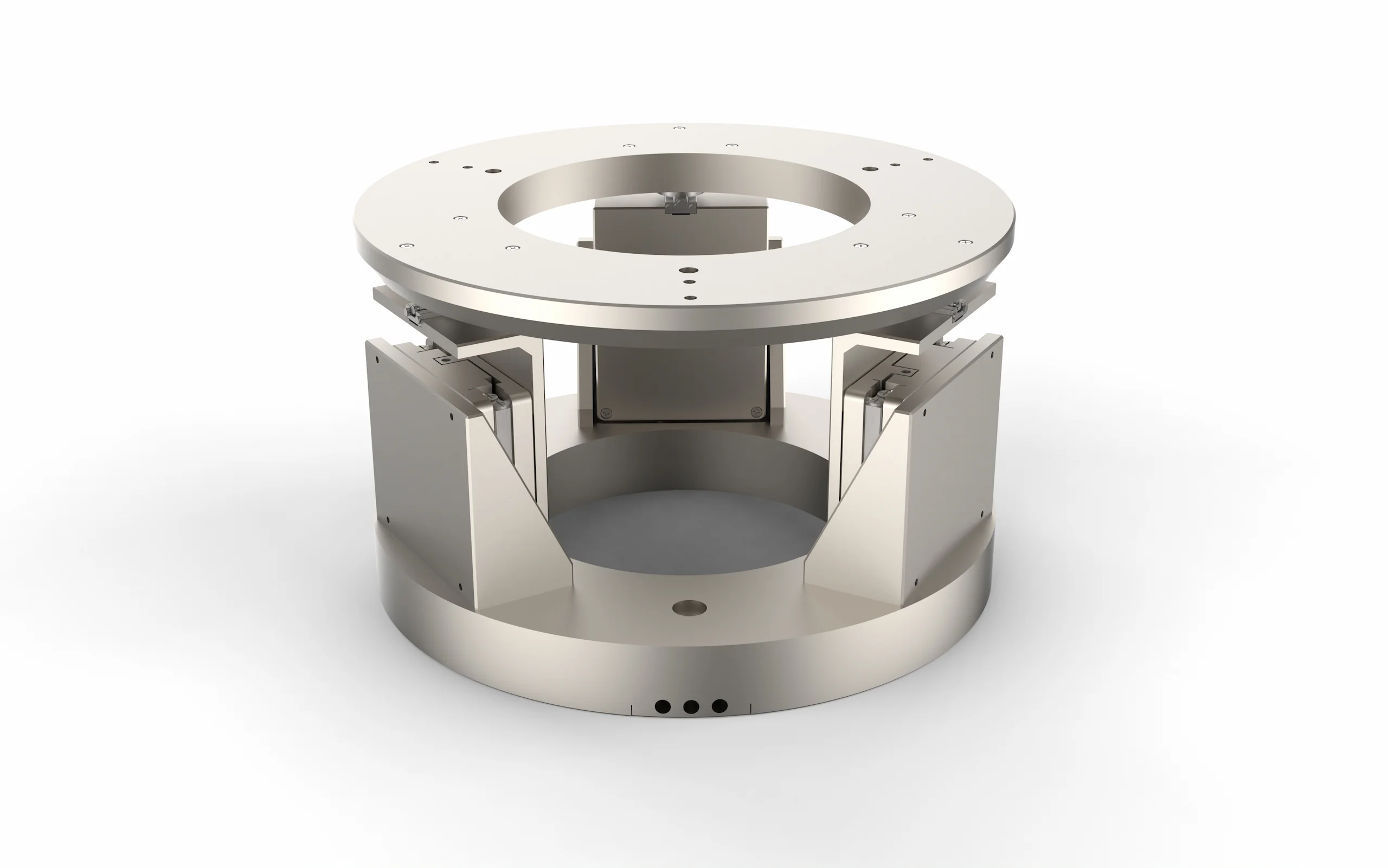
Z alongside X and Y tilt
Adjust height and level a surface
Center and rotate a component in a plane.
Adjust height and level a surface.
Closed-loop nanopositioning
Each piezoelectric stage uses GO piezo walking drives to combine nanometer-scale linear adjustments with millimeter-scale travel. Closed-loop position feedback regulates movement, supporting coarse positioning and fine alignment within one system.
High force density enables GO XYR to position centered top loads up to 10 kg and GO TipTilt to lift up to 2.5 kg. Smooth continuous motion and fast move-and-settle behavior support repeated alignment, while self-locking drives hold position without continuous drive power.
GO piezo walking drives provide 2 nm linear minimum incremental motion together with millimeter-scale travel for coarse positioning and fine alignment in one system.
GO XYR supports centered top loads up to 10 kg during planar motion, while GO TipTilt lifts up to 2.5 kg depending on the selected drive version.
Position feedback regulates smooth continuous movement and supports fast move-and-settle behavior for repeated alignment tasks.
The walking-piezo drives hold position without continuous drive power, including vertical payloads on GO TipTilt.
| Specification | GO XYR | GO TipTilt |
|---|---|---|
| Linear travel | X/Y: ±10 mm | Z: ±10 mm |
| Angular travel | Around Z: ±10° | Around X/Y: ±9° |
| Linear minimum incremental motion | 2 nm | 2 nm |
| Diameter | 165 mm | 150 mm |
| Maximum centered top load | 10 kg | 1 kg or 2.5 kg, depending on version |
| High-vacuum version | Available | Available |
XYR planar alignment
GO XYR combines ±10 mm travel in X and Y with ±10° rotation around Z. Use it when a component must be centered and oriented within the same plane.
The 10 kg rating describes a centered top load supported during planar motion. Select the 8 N or 16 N drive version according to the required push/pull force and loaded speed.
| Specification | GO XYR |
|---|---|
| X travel | ±10 mm |
| Y travel | ±10 mm |
| Rotation around Z | ±10° |
| Linear minimum incremental motion | 2 nm |
| Maximum centered top load | 10 kg |
Motorized tip tilt
GO TipTilt combines ±9° tilt with ±10 mm vertical travel for lifting and leveling samples, optical assemblies and fixtures. Choose the drive version according to payload and loaded speed.
The piezo walking drives combine vertical force with fine adjustment and unpowered holding. Include the fixture and component in the total payload when selecting your system.
| Performance | 15 N | 30 N |
|---|---|---|
| Centered load lifted | 1 kg | 2.5 kg |
| Z speed at maximum top load | >5 mm/s | >1 mm/s |
| Z holding force with power off | 18 N | 33 N |
A motorized tilt stage beneath a suitable mirror fixture can adjust beam direction as well as mounting height.
When selecting a motorized mirror mount or laser beam steering system, match the angular range, payload and required response time to the optical layout.
Control and integration
A GO Controller operates all three drives simultaneously with closed-loop point-to-point control. Connect over USB and use GO software and programming interfaces to integrate motion into your instrument.
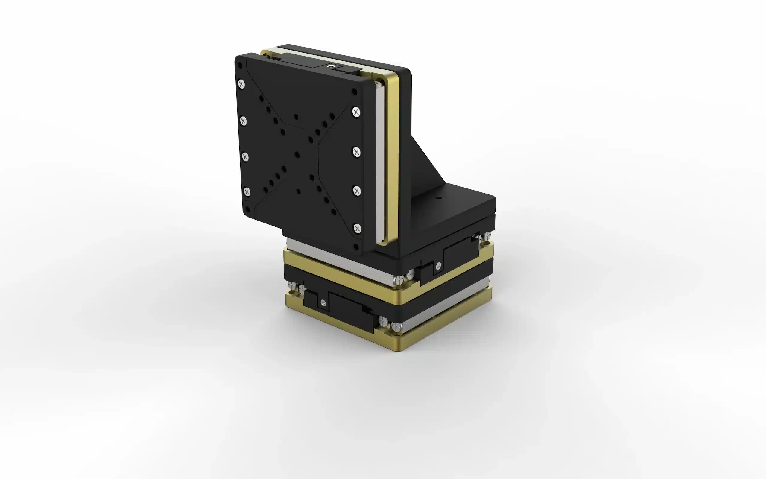
GO XYR and GO TipTilt are complete three-axis configurations with different motion combinations. If your application instead requires X, Y and Z translation, three GO linear stages can be mounted together as a separate GO XYZ assembly—it is an alternative configuration, not an add-on to GO XYR or GO TipTilt.
GO TipTilt supports GO Motion and C++ DLLs. The controller platform also offers Precibeo ASCII Rapid commands, GO Command and LabVIEW drivers. Model-specific data sheets and CAD downloads help you plan mounting and cabling.
High vacuum
10⁻⁴ Pa
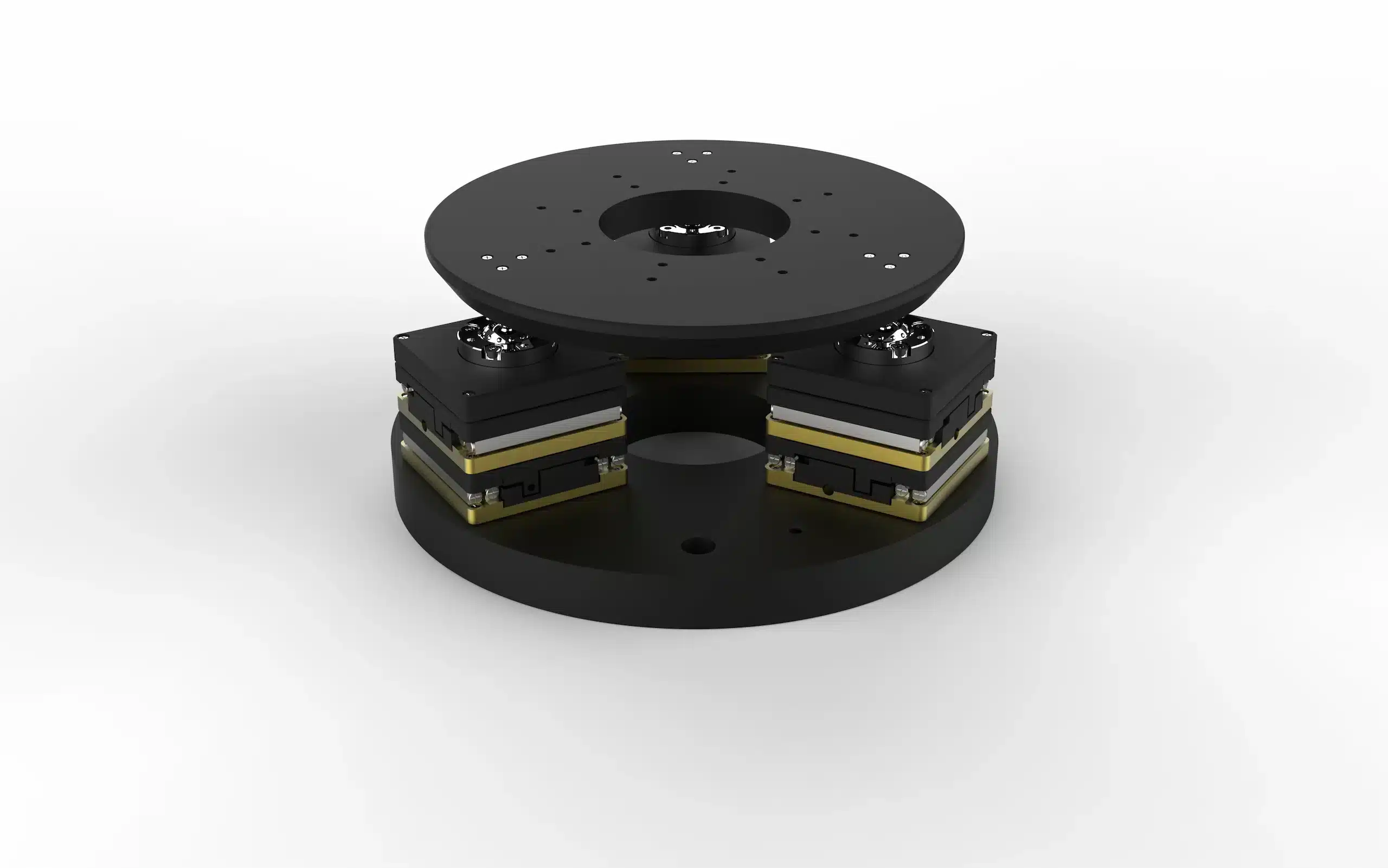
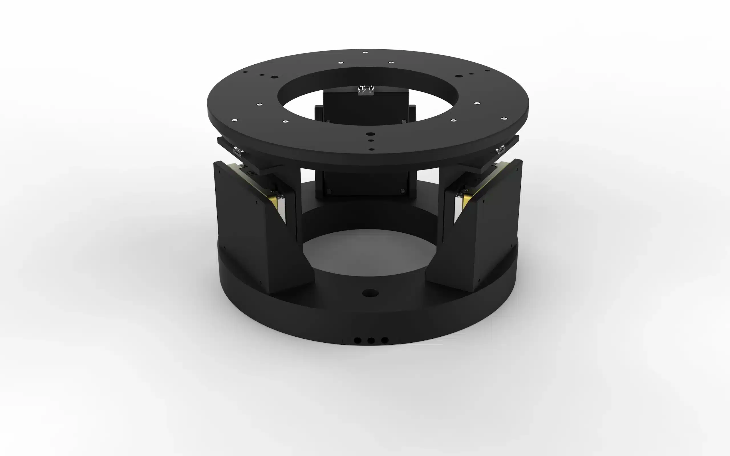
GO XYR HV and GO TipTilt HV support operation down to 10⁻⁴ Pa. Build a high-vacuum positioning system for planar alignment or vertical leveling by connecting vacuum-side cables through chamber feedthroughs to air-side cables and the GO Controller.
Applications
Center optical components, adjust rotation and align mirror fixtures for beam positioning
Align samples and fixtures for inspection or measurement
Adjust sample height, inclination and in-plane orientation
Integrate precise three-axis alignment in ambient or high-vacuum environments
Choose X/Y plus rotation, Z plus two-axis tilt, or XYZ translation.
Match the required linear travel and angular range.
Include the fixture, center of gravity and required speed.
Check the mounting space, interfaces and cable routing.
Select standard or high-vacuum stages, controller and software interface.
Your questions
Three axes can describe different combinations of movement. GO XYR provides X/Y translation and Z rotation; GO TipTilt provides Z translation and X/Y tilt. GO XYZ assemblies provide three linear axes.
Choose a motorized gimbal mount when the main requirement is angular adjustment around a defined pivot point, especially when the optic should remain centered while it rotates. Choose GO TipTilt when the payload needs height adjustment as well as two-axis leveling: it combines Z translation with tilt around X and Y on one load-bearing platform.
The 2 nm specification describes the smallest incremental linear movement. Evaluate positioning accuracy and repeatability separately, alongside the payload and operating conditions.
Choose a six-axis system when your application requires X, Y and Z translation together with rotation around all three axes. Explore GO six-axis stages for complete position and orientation control.
Let’s find your configuration
Tell us the required movements, travel, angular range, payload, center of gravity, speed, mounting space and environment. We will help select the stage, drive version, controller and integration components.
Email info@precibeo.com
or call +46 18 700 13 40